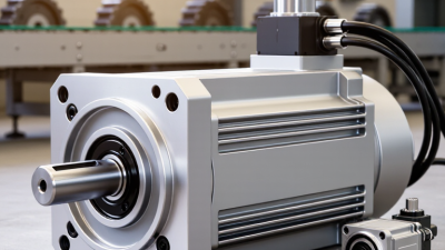
What Is a Direct Drive Servo Motor and How Does It Work?
A direct drive servo motor connects the motor’s rotor directly to the driven load. It removes the gearbox, belt, or other transmission stage commonly used in motion systems. This design can deliver precise torque at low speed. It also reduces backlash, mechanical noise, and maintenance points. Imagine a rotary table turning a heavy camera platform. With direct coupling, the motor controls the table without waiting for gears to catch up. That immediate response is valuable in robotics, machine tools, semiconductor equipment, and packaging lines.
The operating principle is straightforward, although the engineering is not. A servo drive sends controlled electrical current through the motor windings. These currents create a rotating magnetic field. Permanent magnets on the rotor follow that field and produce continuous motion. An encoder reports the rotor’s position to the controller, often thousands of times per second. The controller compares actual movement with the commanded position and corrects errors quickly. This closed-loop process supports accurate speed, position, and torque control.
Direct drive is not automatically the best choice. The motor may need a larger diameter to produce sufficient torque. Its cost, installation requirements, and thermal behavior also deserve careful evaluation. A poorly matched motor can waste energy or respond slowly under changing loads. Real-world selection depends on inertia, duty cycle, allowable error, and the machine’s available space. Measurements matter more than marketing claims. This guide explains how a direct drive servo motor works and where its advantages become practical. Some applications still benefit from gearing. That deserves honest consideration.
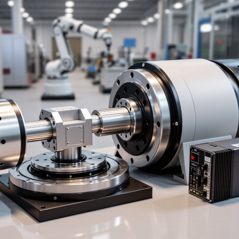
Direct Drive Servo Motor: Definition and Core Characteristics
A direct drive servo motor produces motion without a gearbox or belt between the motor and load. Its rotor connects directly to the machine shaft. This structure reduces mechanical backlash, vibration, and wear. It also improves positioning accuracy during rapid starts and stops.
The motor uses feedback from an encoder to monitor shaft position and speed. A servo drive compares this information with the commanded movement. It then adjusts current several times during operation. Direct torque transfer gives strong low-speed control and smooth movement. High torque density is another core characteristic, especially where compact machinery needs precise force. However, removing the gearbox can increase motor size and purchase cost. A smaller frame is not automatically better. Engineers must check inertia, heat, continuous torque, and peak torque before selection. I have seen performance estimates fail when acceleration time was ignored.
Tips: Match the motor’s continuous torque to the real load, not its advertised peak. Check shaft alignment carefully during installation. Even slight misalignment can create noise and shorten bearing life. Keep encoder cables separated from power cables. This simple detail often prevents unstable feedback. Also test the system under actual load, because unloaded motion can hide poor tuning.
Direct drive systems suit robotic joints, rotary tables, packaging equipment, and precision stages. Their response is fast, but control settings still matter. A technically correct motor can perform poorly with careless tuning. The useful question is not only “How fast?” but “How steadily and repeatedly?”
Main Components and Their Roles in the Motor
What Is a Direct Drive Servo Motor and How Does It Work?
Main Components and Their Roles in the Motor
A direct drive servo motor sends torque straight to the load. It removes the gearbox, coupling stages, and their possible backlash. This structure can improve positioning accuracy and reduce mechanical noise. However, it does not make every machine automatically precise.
The stator contains stationary coils that create a rotating magnetic field. The rotor carries permanent magnets and follows that field. Large bearings support the rotor while handling radial and axial loads. An encoder measures shaft position and speed, often with fine resolution. The servo drive controls current, torque, and motion based on encoder feedback. The motor housing protects these parts and helps transfer heat away. In commissioning work, I check bearing preload and encoder alignment carefully. Small errors there can appear as vibration, heat, or unstable motion. I once underestimated cable routing; electrical noise later affected feedback signals.
Tips: Match the motor’s continuous torque with the real load, not only its peak demand. Check inertia, duty cycle, temperature, and mounting stiffness. Keep feedback cables separated from high-current wires. Cooling also deserves attention. A compact motor may look efficient, yet restricted airflow can reduce its usable torque. Test low-speed movement before running full production cycles. That simple step often reveals alignment problems early. Also, review the encoder resolution against the application’s actual accuracy needs. More counts do not fix a flexible machine frame.
How Torque Is Generated Without a Mechanical Gearbox
A direct drive servo motor produces torque at the load shaft without a mechanical gearbox. Its stator contains controlled windings, while the rotor carries a magnetic field. When the drive sends accurately timed currents through the windings, a rotating magnetic field pulls the rotor around. This interaction creates torque directly.
The control system adjusts current according to the required load and position. A high-resolution feedback device reports the rotor angle, often thousands of times each second. The controller then corrects tiny errors before they become visible motion. More current generally produces more torque, within the motor’s thermal and electrical limits. There is no gear reduction to multiply torque or hide positioning errors.
In practice, this design suits rotary tables, robotic joints, and indexing equipment. The shaft can move smoothly at very low speed, with little backlash and almost no transmission noise. The motor may need a larger diameter to generate useful torque. Heat can also build inside the stator during repeated acceleration. That detail is easy to underestimate.
During commissioning, technicians should check bearing load, feedback alignment, and housing temperature under real duty cycles. A motor can meet its peak torque rating briefly but fail during continuous operation. Direct drive is not automatically better; it shifts more responsibility to sizing, cooling, and control tuning. Small setup mistakes can remain surprisingly expensive.
Feedback Control and Motion-Positioning Process
A direct-drive servo motor moves the load without a gearbox or belt between them. The rotor moves directly. This structure reduces backlash, transmission noise, and mechanical wear. It also gives the controller a clearer connection to the moving part. However, the motor must produce enough torque for the full load, acceleration, and disturbance.
Feedback control makes accurate positioning possible. An encoder measures the shaft angle, speed, or actual load position. The controller compares this feedback with the commanded position. It then calculates the error and adjusts motor current through rapid control loops. A position loop manages destination, while speed and current loops manage motion quality. The process repeats continuously, often thousands of times each second. That gap matters. Even a small error can cause vibration near the target.
During a positioning cycle, the motor accelerates smoothly, approaches the target, and reduces speed before stopping. The controller checks whether the measured position remains within an allowed tolerance. Engineers must tune gains carefully because excessive gain can create oscillation. Low gain may produce sluggish movement. Thermal expansion, changing payloads, encoder resolution, and mechanical flexibility can also affect accuracy. In real installations, perfect positioning is uncommon. Regular calibration and measured testing often reveal problems that simulations miss. A useful design therefore considers the motor, load, feedback device, control settings, and operating environment as one system.
Applications, Advantages, and Operating Limitations
A direct drive servo motor couples its rotor directly to the load, removing gears, belts, and couplings. The motor controls position, speed, and torque through feedback from an encoder. With fewer mechanical links, motion can feel exceptionally smooth. There is no gearbox backlash to hide. During machine commissioning, this difference appears as quieter motion and more predictable positioning. However, the motor must deliver the load’s full torque at the shaft. That requirement shapes every design decision.
These motors suit rotary tables, robotic joints, semiconductor stages, printing equipment, medical positioning systems, and high-speed inspection axes. They work well when accuracy, rapid reversal, and low maintenance matter. Direct coupling also reduces lost motion and mechanical wear. A properly tuned drive can respond quickly to small commands during frequent start-stop cycles. Engineers should verify inertia matching, encoder resolution, thermal capacity, and bearing loads before selecting one. A specification sheet is not enough. Real measurements matter.
The trade-offs are substantial. Direct drive units often cost more and require larger motors than geared systems. Low-speed torque may demand a wider motor diameter or higher current. Heat removal becomes difficult in compact frames, especially during continuous torque operation. External shocks can also reach the bearings because no gearbox absorbs them. Installation alignment must be precise. Poor tuning may create vibration, despite the motor’s theoretical smoothness. In practice, direct drive is not automatically better; its value depends on whether precision outweighs compactness and initial cost.
| Data Dimension | Direct Drive Servo Motor | Practical Notes |
|---|---|---|
| Basic Definition | A servo motor that drives the load directly, without a gearbox, belt, pulley, or other mechanical transmission between the motor shaft and the load. | The motor is selected to provide the required load torque and speed directly. |
| Operating Principle | A servo drive supplies controlled current to the motor windings, creating a rotating magnetic field that produces torque and moves the connected load. | The control system continuously adjusts current, velocity, and position according to feedback. |
| Feedback System | Usually uses a high-resolution encoder or resolver mounted on the motor or load axis. | Feedback accuracy and mechanical installation quality strongly affect positioning performance. |
| Common Motor Forms | Direct-drive rotary motors and direct-drive torque motors. Linear direct-drive systems use a similar principle without rotary-to-linear transmission components. | The appropriate form depends on whether the application requires rotary or linear motion. |
| Typical Speed Range | Commonly optimized for low-to-moderate speed operation, often from near-zero speed to several hundred revolutions per minute; some designs operate at higher speeds. | The actual range depends on motor construction, load inertia, cooling, drive settings, and required torque. |
| Torque Capability | Designed to deliver high continuous and peak torque at relatively low speed compared with many conventional servo motors paired with gearboxes. | Continuous torque is limited by thermal capacity; peak torque is normally available only for short periods. |
| Positioning Accuracy | Can provide very high positioning accuracy because gearbox backlash, belt elasticity, and transmission compliance are removed. | System accuracy still depends on encoder resolution, bearing runout, structural stiffness, calibration, and control tuning. |
| Backlash and Compliance | Essentially eliminates transmission backlash and reduces torsional compliance associated with mechanical reduction systems. | The machine structure and coupling must still be sufficiently rigid to prevent deflection. |
| Response and Controllability | Provides fast torque response and precise control of acceleration, deceleration, velocity, and position. | Low reflected inertia and direct load feedback can improve dynamic response when the system is correctly tuned. |
| Mechanical Efficiency | Generally high because power is not transmitted through gears, belts, or other reduction elements. | Overall efficiency also includes motor copper losses, iron losses, bearing losses, and servo-drive losses. |
| Maintenance Requirements | Lower mechanical maintenance because there are fewer wear-prone transmission components. | Bearings, seals, feedback devices, cooling systems, wiring, and mounting surfaces still require inspection. |
| Noise and Vibration | Usually produces less mechanical noise and vibration than systems using high-ratio gearboxes or belt drives. | Electrical harmonics, cogging torque, bearing condition, imbalance, and servo tuning can still generate vibration. |
| Thermal Management | May require natural convection, forced-air cooling, or liquid cooling, particularly in compact high-torque designs. | Allowable continuous torque decreases when ambient temperature or installation restrictions limit heat dissipation. |
| Installation Requirements | Requires accurate shaft alignment, adequate bearing support, correct coupling design, proper grounding, and suitable feedback wiring. | Misalignment or insufficient structural stiffness can reduce accuracy and shorten bearing life. |
| Typical Applications | Rotary tables, indexing mechanisms, semiconductor equipment, printing machinery, machine tools, robotics, medical equipment, inspection systems, and precision winding equipment. | Especially suitable for applications requiring precise low-speed motion, rapid reversal, high repeatability, or direct load positioning. |
| Key Advantages | High torque density, low backlash, strong repeatability, fast dynamic response, reduced mechanical complexity, low mechanical noise, and potentially lower maintenance. | Benefits are greatest when precision and dynamic performance are more important than minimum initial purchase cost. |
| Operating Limitations | Higher motor cost, larger diameter in some designs, sensitivity to heat, demanding mounting requirements, and limited ability to trade speed for torque through mechanical reduction. | A conventional servo motor with a gearbox may be more economical when high output speed, compact axial dimensions, or very high torque multiplication is required. |
| Selection Factors | Required continuous torque, peak torque, speed, acceleration, load inertia, duty cycle, allowable temperature rise, positioning accuracy, environmental conditions, and available mounting space. | Motor sizing should use the complete motion profile rather than only the maximum load or maximum speed. |
| Best-Fit Operating Profile | Frequent starts and stops, rapid acceleration, precise indexing, smooth low-speed rotation, and direct control of a high-inertia or precision load. | The motor must be matched to the load inertia and the required duty cycle to avoid overheating or unstable control. |
Related Posts
-
How to Choose the Right Industrial Servo Motor?
-
How to Choose an Electric Servo Motor in 2026?
-
Top Tips for Choosing the Right Integrated Servo Motor?
-
Unlocking Efficiency: How Industrial Servo Motors Transform Automation in Manufacturing
-

How to Choose the Right AC Servo Drive for Your Machine?
-
Electric Servo Motor Showdown: Which Type Reigns Supreme in Performance and Efficiency?