
What Is a DC Servo Motor and How Does It Work?
A dc servomotor turns electrical commands into controlled mechanical motion. Unlike a basic DC motor, it does not simply spin when voltage rises. An encoder or resolver reports position and speed. A controller compares that feedback with the target. The drive then adjusts current, torque, and direction. Precision lives in this closed loop.
The market is expanding. Grand View Research reports that the global servo motors and drives market could reach approximately USD 23.6 billion by 2030, with automation supporting continued growth (Grand View Research, Servo Motors and Drives Market Size, Share & Trends Analysis Report, 2024–2030). Fortune Business Insights also identifies robotics, packaging, electronics, and factory automation as major demand areas. These figures describe a broad servo market, not dc servomotor sales alone. That distinction matters.
Richard C. Dorf, a respected control-systems authority, defines the principle clearly: “A servomechanism is a feedback control system in which the output is mechanical position, velocity, or acceleration” (Modern Control Systems, with Robert H. Bishop). His definition remains useful on a factory floor. Imagine a conveyor axis stopping within a fraction of a millimeter. The motor moves. The sensor checks. The controller corrects.
Small errors still matter. Heat, brush wear, backlash, electrical noise, and poor tuning can reduce performance. A datasheet cannot reveal every installation problem. This article examines how a dc servomotor works, how its feedback loop behaves, and where engineers must question attractive specifications.
Definition and Core Characteristics of a DC Servo Motor
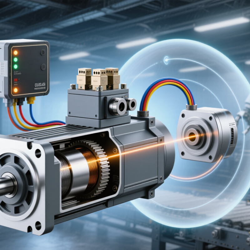
A DC servo motor is a motor designed for controlled motion rather than simple continuous rotation. It combines a DC motor, feedback sensor, controller, and often a gear train. The sensor measures position or speed during operation. The controller compares that measurement with the requested value. It then adjusts the motor’s voltage through a driver circuit. This creates a closed-loop system.
Core characteristics include accurate positioning, quick response, and controllable torque. A small encoder may report shaft movement many times per second. In a robotic joint, the motor can move a mechanism to 45 degrees and hold it there. If the load shifts, the controller detects the error and corrects the current. That correction is not magic. It depends on sensor resolution, wiring quality, and suitable control settings.
Real performance also depends on load inertia and friction. A motor may appear precise without a load, then overshoot under real conditions. This is where testing matters. Brushed DC servo motors can deliver strong starting torque, but their brushes wear over time. Brushless designs reduce that maintenance issue, yet they need more complex electronic control. Engineers should check rated torque, peak current, speed range, and feedback accuracy before selection. I have found that a generous safety margin helps, although excessive sizing can reduce responsiveness and increase cost. Some systems still show a small dead zone near the target. That detail is easy to overlook.
What Is a DC Servo Motor and How Does It Work? - Definition and Core Characteristics of a DC Servo Motor
| Dimension | Description | Typical Characteristics or Values | Practical Significance |
|---|---|---|---|
| Definition | A DC servo motor is a direct-current motor used in a closed-loop motion-control system. | Combines a motor, feedback device, controller, and power amplifier or drive. | Provides controlled position, speed, or torque rather than simply continuous rotation. |
| Energy Conversion | Converts electrical energy supplied as direct current into mechanical rotary motion. | Torque is generated by the interaction between the magnetic field and armature current. | The motor can accelerate, decelerate, and reverse according to control commands. |
| Main Motor Parts | Includes the stator, rotor or armature, windings, commutator, brushes, bearings, and shaft. | Brushed construction uses mechanical commutation between brushes and commutator segments. | The mechanical components determine efficiency, service life, noise, and maintenance needs. |
| Feedback Device | Measures shaft position, rotational speed, or both for comparison with the command signal. | Common options include an encoder, tachometer, or resolver. | Feedback allows the controller to detect error and correct motion in real time. |
| Control Structure | A closed-loop controller continuously compares the reference command with measured output. | Position, velocity, and current or torque loops may be nested together. | The system compensates for load changes, friction, and disturbances. |
| Operating Principle | The controller adjusts armature voltage or current to reduce the difference between commanded and actual motion. | A larger position or speed error generally produces a stronger corrective control signal, within system limits. | Accurate motion is achieved through continuous measurement and correction. |
| Speed Control | Motor speed is primarily related to applied armature voltage and is affected by load and back electromotive force. | Speed can be regulated over a wide range, depending on motor and drive design. | Suitable for applications requiring stable speed under changing loads. |
| Torque Control | Motor torque is approximately proportional to armature current within the normal operating region. | Torque output is limited by current rating, thermal capacity, and mechanical design. | Enables controlled force, tension, acceleration, and dynamic response. |
| Position Accuracy | Position accuracy depends on feedback resolution, controller tuning, mechanical compliance, and load conditions. | Higher-resolution feedback generally improves measurable position resolution, but does not eliminate mechanical error. | Important for indexing, pick-and-place, machine tools, and robotic mechanisms. |
| Dynamic Response | Describes how quickly the motor responds to command changes or disturbances. | Influenced by rotor inertia, load inertia, torque-to-inertia ratio, current-loop bandwidth, and tuning. | Fast response improves acceleration and settling time but may require careful control tuning. |
| Back EMF | A voltage generated by the rotating armature that opposes the applied voltage. | Back EMF generally increases with motor speed. | It helps explain the relationship between speed, voltage, current, and load torque. |
| Power Supply | Supplies controlled DC power to the motor through a servo amplifier or drive. | Common system voltages include 12 V, 24 V, 48 V, and higher industrial DC bus voltages. | The selected voltage must match the motor, drive, insulation, and application requirements. |
| Efficiency Considerations | Efficiency is reduced by winding resistance, brush friction, bearing friction, magnetic losses, and drive losses. | Efficiency varies with speed, torque, operating temperature, and load point. | Thermal management and correct sizing are essential for continuous operation. |
| Advantages | Offers precise controllability, strong starting torque, and relatively simple speed control. | Well suited to low- and medium-power motion systems with frequent changes in speed or position. | Can provide predictable motion when properly matched with feedback and a controller. |
| Limitations | Brushed motors experience brush and commutator wear and may produce electrical noise or sparking. | Requires periodic inspection or replacement of wear components in demanding applications. | A brushless servo motor may be preferred where low maintenance and high cleanliness are priorities. |
| Typical Applications | Used where controlled rotary motion, repeatability, or rapid adjustment is required. | Robotics, conveyor positioning, laboratory instruments, camera mechanisms, printers, and automated machinery. | The closed-loop design supports repeatable movement and correction of operating errors. |
Related Posts
-
Innovative Solutions for Achieving Maximum Efficiency with Best DC Servo Motors
-

Top 10 Benefits of Using DC Servo Drives in Industrial Applications
-

How to Choose the Right Small Servo Motor for Your Project?
-
How to Choose the Right Industrial Servo Motor?
-

Top Small DC Motor Applications and Buying Guide for Beginners
-

Electric Servo Motor Showdown: Which Type Reigns Supreme in Performance and Efficiency?